Vertex Operations (Vertex Shader)
This section describes the vertex operations.
Vertex operations apply lighting and shading to individual vertices based on information and vertex attributes from the vertex buffer.
The process is also called the vertex shader.
Vertex attributes
This section describes the types and roles of vertex attributes.
Types of Vertex Attributes
Vertex attributes refers to a type of data handled for each vertex. Polygon models are made up of vertex attributes.
Up to 12 vertex attibutes can be set for each vertex.
The table below lists some of the vertex attributes that make up a model shape.
| Types of Vertex Attributes | Description |
|---|---|
| Vertex coordinates | Represents the coordinate information used to indicate the position of each vertex making up a polygon surface. A polygon surface is configured from at least 3 vertices. |
| Normal vector | Represents information used to indicate the orientation of each vertex making up a polygon surface. This can be used for the shading process performed by lighting. |
| Texture coordinate 0 | Represents coordinate information used to align the position of the texture image with each vertex making up the polygon surface. Up to three texture coordinates can be used with CreativeStudio. |
Vertex color |
Represents information that indicates vertex color. You can directly specify a color using a 3D graphics tool or store the color resulting from lighting. |
Vertex Shader Processes
The vertex shader executes three processes on vertex attributes input from the vertex buffer.
The table below lists the roles played by the vertex shader.
| Shader Roles | Description |
|---|---|
| Coordinate Transformation | Coordinates are converted to window coordinates used for on-screen display and output based on the vertex coordinate and normal vector used as input. |
| Generating Texture Coordinates | Vertex coordinates used for texture mapping are generated and output based on the vertex information used as input. |
| Vertex Color Generation | Vertex colors are generated based on the result of the lighting process and output based on vertex information used as input. |
To follow are several examples of vertex shader processes. The description covers processing from the input of each vertex attribute, through the vertex shader and rasterizing processes, and up to output to the fragment shader.
Rasterization is a process that converts polygons composed of vertices into pixels handled on a per-fragment basic. This fragment information is then passed on to the fragment shader.
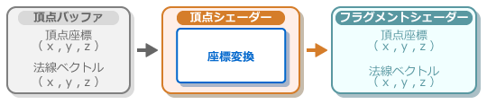
Coordinate Transformation
Conversion to the on-screen coordinate system and output
In the process flow shown below, the vertex shader takes the input vertex coordinates and normal vector, performs a conversion to a coordinate system that can be displayed on screen, and outputs the result.
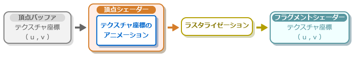
Texture coordinate 0
Texture coordinate output
In the process flow shown below, the vertex shader generates texture coordinates for animation based on the texture coordinates that are input, and this is then rasterized and output.
Output of texture coordinates for environment mapping
In the process flow shown below, the vertex shader generates texture coordinates for environment mapping based on the normal vector that is input, and this is then rasterized and output.

Output of texture coordinates for projection mapping
In the process flow shown below, the vertex shader generates texture coordinates for projection mapping based on the vertex coordinates that are input, and this is then rasterized and output.

Vertex color
Output vertex colors as-is
The following figure shows the process flow up to the output of vertex colors as-is without processing of vertex colors used as input by the vertex shader.

Output of vertex lighting results
The following figure shows the process flow from execution of the vertex lighting process by the vertex shader based on the normal vector used as input up to the output of the result as the vertex color.

Geometry Shader

Triangle Setup
This section describes how the triangle setup process forms polygon models.
Polygon Assembly
Exclusion of Unneeded Polygons by the Clipping Process