This chapter describes procedures and precautions for creating models using NintendoWare with Softimage.
Nodes
Null
Implicit Objects
Chains
Polygon Meshes
Materials
Textures
Envelopes
Softimage nodes support Model, Null, Skeleton (root, bone, effector), and Polygon Mesh.
Although under Softimage it is possible to give the same name to more than one node as long as the model node of the parent differs, nodes having the same name must not exist inside an cmdl file.
Hence, there is a possibility of duplicate names whenever more than one Model node exists. If more than one node with the same name is present, the node highest in the hierarchy is output using that name, but other nodes with that name are output with an underscore and a number (such as "_1" and "_2") appended to the end. If more than one node exists at the same hierarchical depth, they are output in alphabetical order.
There is always one root node in a cmdl file.
For this reason, one Model node is output as-is as a root node. 3D objects (not belonging to the Model node) immediately below Scene_Root are output together as a single root node having the name nw4r_root.
| Be sure to set 1 for the environmental variable NW4C_NOT_REMOVE_INEFFECTIVE_NODE if you want to restore output specifications for Nw4cRoot used in 0.5.4 and earlier versions. |
When exporting, the center of each node is recognized as the local coordinate origin. If a Pivot is moved or rotated in Softimage or if it has animations, it may not export properly.
Outputs the status of the visibility property of each node (View display/hide (View Visibility)).
Control objects (icons related to dynamics such as gravity and wind) and deformation icons for things like lattices and waves are not output. In addition, nodes below control objects are not output.
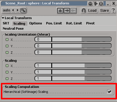
Although it is possible in Softimage to turn settings on and off at the node level (inside Local Transform Properties), as with Classic Scaling of SOFTIMAGE|3D, these properties are set for the entire model.
If hierarchical scaling is turned on for all nodes to be output to the intermediate file, they are output with this feature turned on. If all nodes are turned off, they are output with this feature turned off. An error is output if there is a mixture of nodes having this feature turned on or off.
Output as a single node.
An implicit object is a dummy object used to control envelopes and animations that is often used for character rigging. Implicit objects are output as a single node.
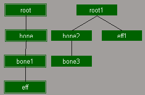
Elements of a chain used to configure a skeleton (root, bone, effector) are each output as a node.
Although chains can be created by either the SI3D method or XSI method in Softimage, the Export plug-in supports either method.
The chain to be drawn can be switched using Create > Skeleton > SI3D Skeleton Drawing.
Output as a single node.
When polygons are output to the intermediate file, the Export plug-in operates internally to divide the polygons into triangles for output.
The number of vertices that can be exported to an intermediate file is greater than the number possible on the DCC tool. Although this differs depending on the mesh structure, it is three times the maximum number of triangular polygons.
The vertex color of models for which a vertex color has been set can be output to the intermediate file.
Only the first vertex color is supported by the Export plug-in.
In Softimage, vertex colors cannot be applied only partially to an object. The entire object must have a vertex color.
The alpha component of a vertex color is reflected at time of output because it is handled differently by CTR and Softimage.
If the output option Invert VertexColor Alpha is selected, the alpha is inverted and the value under Softimage is output as-is.
Under Softimage, It is possible to apply the vertex color to rendering by connecting the Vertex_rgba node. However, the output is made as described above due to the differences in how the alpha component is handled compared with CTR. Since the Exporter does not check if the Vertex_rgba node is connected, be sure to connect the Vertex_rgba node only when you want to apply the vertex color to the rendering screen shown under Softimage.

In addition, you can control the format of the vertex color that is output by attaching a suffix to the vertex color property name.
Output in RGB format by appending _rgb to the end of the name, or output in RGBA format by appending _rgba to the name.
If nothing is appended, it is output in RGBA format.
If nothing is appended the four elements RGBA will be output even if you are not using the vertex color alpha. So in order reduce the data size when you are not using the vertex color alpha, append _rgb to the name so only the three elements RGB are output.
The vertex color property name is located as shown below:

If a vertex color property having any of the following names exists, the color of that vertex color property can be output as a user vertex attribute.
「nw4cUser0
nw4cUser1
nw4cUser2
(only the U is uppercase)
The color set can be freely used by any game as a user vertex attribute.
The precision of output data is 32-bit floating point if the suffix of the above color set name is _f, 16-bit integer precision if the suffix is _s, and 8-bit integer precision if the suffix is _b or there is no suffix. For example, be sure to set the color set name to "nw4cUser0_s" if you want to output the 0th user vertex attribute as a 16-bit integer.
Four components (RGBA) are output by default for the number of data components per vertex.
In addition, if a 2 is included before the letter indicating precision in the suffix of the vertex color property name, the number of data components per vertex is 2. For example, be sure to set the color set name to "nw4cUser1_2f" if you want to output the 1st user vertex attribute as a 2-component 32-bit floating point number. Similarly, use "_2s" for 16-bit integers and "_2b" for 8-bit integers.
In Softimage, there is a normal usually held by the object and a user normal. The user normal can be set using the XSI_UserNormalEditing plug-in (XSISDK/examples/workgroup/Addons/XSI_UserNormalEditing).
Under Softimage 2010, this can also be set using the User Normal Adjustment Tool.
Normally, the regular object normal is output, but the user normal is output for objects that have user normals (that have Cluster - User_Normal_Cluster).
If instances are used, they are exported in the same state as instantiated instances.
Envelope model instances are not supported.
If clones are used, they are output as-is as separate objects. Since materials can also hold unique materials, material processing identical to regular objects is performed.
Under NintendoWare, a group of polygons assigned the same material is called a mesh.
The rendering order of meshes can be controlled using the render priority set for the material.
The rendering priority is set using the NW4C Set Render Priority plug-in.
One material per group that shares the same material is output to the intermediate file.
The name set under Softimage is output in the intermediate file as-is.
If a single material is connected with multiple shading groups, the material used with the first exported node is exported with its original name, but the names of other materials are exported with an underscore and a numeral appended to them ( "_1", "_2" and so forth).
If the same material is used by an object without vertex color and an object with vertex color, it is output as different materials. Materials used in nodes that are exported first are exported with their original names, whereas materials used with nodes that are exported later are exported with an underscore and a numeral appended to their names.
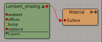
Converts shader nodes to be connected to the surface node of the material node. Also converts Lambert (or Simple Lambert), Phong (or Simple Phong), Blinn shader (or Simple Blinn), constants and anisotropic.
→ (See Texture Render Tree)
The following attributes are reflected in the intermediate files.
Diffuse - Enable is off.Specular - Enable is off.
Incandescence - Enable, the color black is output.
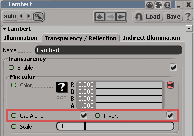
Transparency - Enable is off. Outputs the Alpha value if Transparency - Enable is on and UseAlpha is also on.UseAlpha is off. Invert is also reflected in the value at this time.Transparency element in the material.
Tangent information is required in order to use the anisotropic shader.
Tangent information is generated from vertex UV data. However, the UV data used to generate it is determined according to the following rules. A check is made if textures are connected in the order Diffuse -> Ambient -> Specular -> Transparency -> LayerTexture. The UV data referenced by the first valid texture found is used.
However, the UV data referenced by the normal map is used if there is a normal map.
If no valid texture is found, tangent information is not output.
If a global material and a local material both exist for a single polygon object, both materials are output.
Having more than one local material is also supported.
The texture's filename minus the extension is exported as the texture name. Do not use double-byte characters or half-width kana in a texture file name.
A single texture and texture layer is supported.
For the texture layer, up to three textures are supported.
If more than one texture is connected to a material, only the texture coordinate being used is output to the intermediate file. Because there can be as many as three textures per material, there can also be as many as three texture coordinates.
If you use TGA files that have additional information for NintendoWare, the format and texture data recorded in that additional information will be applied to intermediate files.
Currently, TGA files that have additional information can be created using the NintendoWare for CTR Photoshop plug-in. For instructions on using the NintendoWare for CTR Photoshop plug-in, see NintendoWare for CTR Photoshop Plug-in Manual.
In addition to TGA files that have additional information, all textures of file types that support image nodes can be used. Note, however, that mipmaps cannot be used in this case.
Both the height and width of the texture image must be set to a power of two equal to or greater than 8 and equal to or less than 1024.
When using TGA files that have additional information, the texture format used is the one specified in the additional information.
When using texture files that do not have additional information, the format is determined automatically based on the following rules. At this time, a value of 255 for the 8-bit alpha value of the texture file represents opaque, 0 represents transparent, and a value from 1 to 254 is taken as a translucent texel.
HILO8 is used for the format for normal map textures without additional information.
The following attributes are reflected by texture-related properties:

ScalingU, ScalingV, RotationW, TranslationU, and TranslationV of the UVW Transformation are output to an intermediate file. Texture SRT and repeat are possible using the UVW Transformation without having to change the texture coordinate set for the vertex.ScalingW, RotationU, RotationV, and TranslationW) are not reflected in the intermediate file. If values other than initial values are set for these parameters, the display shown in Softimage might not match that shown in NW4C.Scaling, Rotation, and Position parameters of Texture_Support are not referenced. If values other than initial values are set for these parameters, the display shown in Softimage might not match that shown in NW4C .Image node to All before performing editing. An error results if a different texture array and repeat setting is used for each object. If you want to use a different texture array and repeat setting for each object, be sure to set a different material for each object.
| There is no support for Mirror. If you want mirrored display of textures, configure the settings using 3DEditor (CreativeStudio). |
The following parameters are convertible for the structure of the render tree:
A shader value is output for diffuse, specular, and incandescence.
If color animation is set fordiffuse, specular, and incandescence, the file can be output as a material color animation (cmata) file. If the shader does not have a specular element, the color black is output.
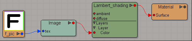
In the example shown in the figure below, a shader color is output for diffuse, and black is output because there is no specular element.
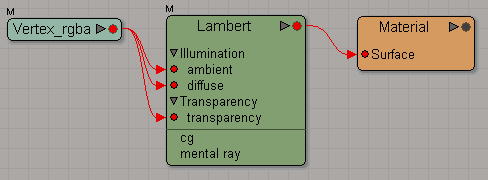
If a vertex color is set for a model, the vertex color is output to the intermediate file whether or not the Vertex_rgba node has been connected.
If the Vertex_rgba node has been connected to diffuse or ambient, a fixed color (white for diffuse and ambient and black for specular) is output for that color element.
Furthermore, if some node is connected to diffuse and/or specular, the element(s) are not output to the cmata file, even if color animation is set for them.
In the example shown in the figure below, vertex color is output, and white is output for diffuse, whereas black is output for specular. Even if color animation has been set to diffuse, the element is not output to the cmata file.

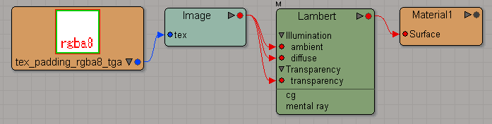
If the Vertex_rgba node is connected as shown in the example in the figure, the vertex color can be confirmed on the rendering screen in Softimage. In addition, the alpha component of the vertex color can be assigned to transparency by configuring for transparency input and turning Use Alpha on. However, be sure to turn Invert on because CTR handles alpha in the opposite way from Softimage.
Colors can be freely set, even for diffuse, ambient, and specular, by setting a texture for the texture layer.
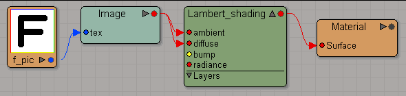
In the example shown in the figure below, a shader color is output for diffuse and ambient while a texture is being applied. Black is output, since there is no specular element.
Up to three textures can be connected to the texture layer.
A texture is output, even when the Image node is directly connected to diffuse the shader.
As in the example shown in the figure, it is possible to assign the alpha component of the texture image to transparency by setting transparency input and turning on Use Alpha. Settings can be confirmed on the rendering screen in Softimage. However, be sure to turn Invert on because CTR handles alpha in the opposite way from Softimage.
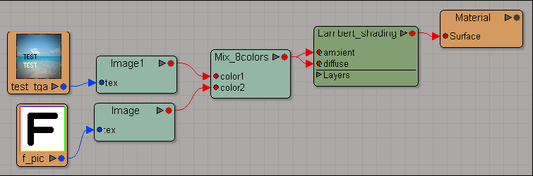
As an example other than those described above, multiple textures connected to the Mixer node are output if a node such as Mix_2colors or Mix_8colors is connected to diffuse and multiple textures have been set.
Output is made in the same manner as when multiple textures have been set using the texture layer.
Even if ambient and diffuse are connected to multiple parameters at this time, Mixer nodes are output only once.
Also, only one Mixer node can be used within a material.
In the example shown in the figure below, output is made with test_tga, connected to color1 of Mix_8colors, and f_pic, connected to color2 of Mix_8colors, applied as textures.
| Parameters may not be reflected normally if set outside the range given in documentation. |
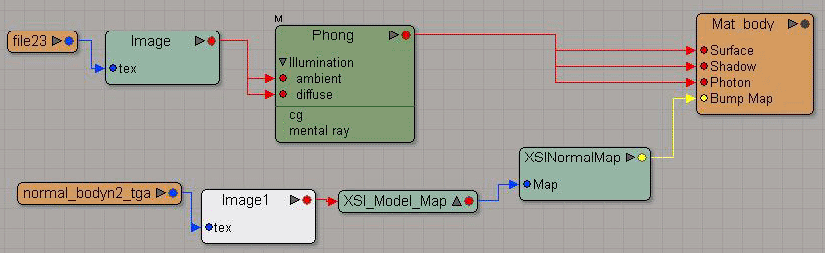
| CTR uses tangent space normal textures. |
The determination about setting a normal map is based on the existence of the connections to BumpMap input of the material node.
The normal map takes the texture specified by the ImageClip node, detected by going through BumpMap -> XSINormalMap -> XSIModelMap -> Image input. The normal map outputs the texture in the RGBA8 format. Additional information of the texture is not reflected.
The Export plug-in supports envelope model output.
The envelope weight (weight value) set for each vertex is output to the intermediate file as a value ranging from 1 to 100% (where the fractional part is rounded to the nearest integer). An error is output if a negative value less than zero or a positive value greater than 100 is set, or if values that do not add up to 100% are set. (However, this excludes errors of less than 1%.)
Up to four weights can be set for a single vertex. If more than four weights are set, only four weights will be used in order of largest, and other weights will be ignored.
CONFIDENTIAL