Texture Mapping
This document describes the properties of the different kinds of texture mapping that is possible using texel operations.
To read details texel operations, see here.
A texel operation computes the correspondences between an image that was input into texture memory and the texture coordinates that were input from a vertex shader.
Interpolation that smooths out the appearance of texture images is also done during this process.
Procedural textures (a way of generating textures automatically) are also generated by texel operations.
Texture Mapping Types
This section describes four types of mapping methods that can be used with CreativeStudio.
Mapping Using Texture Coordinates
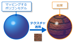
Mapping using texture coordinates is the most typical mapping method.
Texture coordinates are the coordinates used when applying texture images to a polygon model. This is called "texture mapping." With texture coordinates, the bottom left corner is taken as the origin of the texture image. The positive direction for the U-coordinate is toward the right and the positive direction for the V-coordinate is toward the top. Regardless of the size, the texture is applied within a range of 0.0 and 1.0 in both the U direction and the V direction.
The following figure shows the texture coordinate system with the bottom left of the texture image as the origin.

The following figure represents a conceptual image of mapping using texture coordinates.
UV Sets
A UV set is a set that associates a texture image with the texture coordinates for each vertex.
Mapping Using Camera Cube Coordinates
This mapping method uses camera cube coordinates.
Camera cube coordinates are texture coordinates generated by texel operations based on the polygon model's normal data and the camera coordinate system. This mapping method allows expressions where the surrounding scenery is reflected when the viewpoint is changed by referencing a single texture image that includes image information for each of the six directions surrounding a polygon model.
The figure below shows a texture mapped using camera cube coordinates.

The figure below depicts how a texture is applied in camera cube coordinates.
The picture is the image of a shiny sphere model in a cubic box.

Mapping Using Camera Sphere Coordinates
This mapping method uses camera sphere coordinates.
Camera sphere coordinates are texture coordinates generated by texel operations based on the polygon model's normal data and the camera coordinate system. This mapping method allows expresions where the surrounding scenery is reflected by referencing a single image that should be reflected by a polygon model. There are no changes to the image being reflected when the viewpoint position changes.
The following figure represents a conceptual image of mapping using camera sphere coordinates.

Mapping Using Projection
This mapping method uses coordinates for projection.
Coordinates for projection are texture coordinates generated by texel operations based on vertex coordinates loaded from the vertex buffer. All texture coordinates generated for the texture image are mapped within a range of 0.0 and 1.0 in both the U direction and the V direction. Expressions such as image projections and shadows are possible.
The following figure represents a conceptual image of mapping using projection.
How the Projection Texture Process Works
There are three calculation methods required when generating projection texture coordinates.
The table below lists these three calculation methods.

Bump mapping
This section describes types of bump mapping.
Bump map
Bump mapping is a feature for expressing quasi-bumps and indentations using textures and shifting the normal for each fragment.
You can use bump maps to express roughness on the surface of a polygon model, turning a simple model made from a few polygons into what appears to be a more complex model when rendered.
The figure below shows the use of bump mapping.
How Bump Maps Work
In bump mapping, the RGB values for each texel in the image are matched to the XYZ coordinates of the normal vector.
The value 128 is treated as the center value for each RGB color component. Values between 0 and 127 are treated as negative, and values between 129 and 255 are treated as positive.
Tangent map
Tangent mapping is a feature for expressing quasi-reflection using textures and shifting the tangent for each fragment.
Tangent mapping is mainly required for anisotropic reflections. Anisotropic reflections are reflections that exhibit directionality and they are apparent everywhere in everything from shiny hair to brushed-metal surfaces.
The directionality of the reflection depends on the direction of the tangent, and tangent mapping involves the shifting to the direction of the tangent.
The figure below shows the use of a tangent map.
How a Tangent Map Works
In tangent mapping, the RG values for each texel in the image are matched to the XY coordinates of the tangent vector.
In tangent mapping of fragment lighting, the value entered for the B component is not used because the tangent does not have a Z component.
The value 128 is treated as the center value for each RG color component. Values between 0 and 127 are treated as negative, and values between 129 and 255 are treated as positive.
Recalculating the Z Component
When you use the feature to recalculate the normal, the Z component is recalculated from the X,Y components (i.e., the texture's B component is not used for the vector's Z component).
In most cases, you get a better result than if you recalculated using the texture's B component.
You must enable this recalculation feature if you are going to use a HILO format texture with just R and G components for normal vector bump mapping.
However, if you choose to use tangent mapping for anisotropic reflections and the like, we recommend that you do not use this feature.
The reason is because it is presumed that tangents that do not have a Z component will be for tangent mapping of fragment lighting.