Creating Cube Maps
Here, we describe how to create a cube map using a DCC tool and checking it under CreativeStudio.
The following three cube mapping methods will be described.
- Projecting a scene onto a cube and baking the texture
- Rendering six directions using a camera
- Creating a cube map from an image
The Difference Between a Cube Map and a Hemisphere Map
The image prepared for a hemisphere map is only 180 degrees as seen from the camera and the image reflected in models is always the same as seen from any angle. However, because the image prepared for a cube map is a full 360 degrees, cube maps allow the expression of reflections that vary based on the angle of view.
This page describes how to create a cube map for a fully reflective model.
Maya is used as the DCC tool in this description.
DCC tool is an acronym for Digital Content Creation.
Maya, XSI, Photoshop and other such applications are examples of digital content creation tools.
Creating a Cube Map With a DCC Tool (Part 1)
Projecting a scene onto a cube and baking the texture
The cube map is projected onto a cube.
Load the scene to be projected
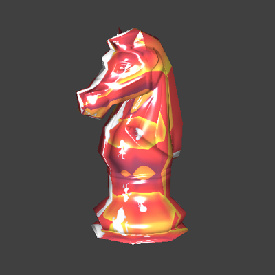
Here, we will create a scene with easy to understand directionality as an example.

Create a cube in any location and adjust the direction of projection to match the cube UV
Place the cube in a location that surveys the scene.
The size of the cube does not matter because the images inside the each of the areas given by connecting the cube center to each of its vertices is projected onto each surface of the cube.
However, take care that the cube does not intersect with any background objects.
In the case of the default cube, enter (0, 0, -90) for the rotate and enter freeze for the transform.
The default cube UV is not configured so the floor and ceiling reflect in the T-shaped part that sticks out, so this must be corrected.
Although you can also adjust the UV manually, manual adjustment requires great care because there is a possibility of making a mistake in the orientation used for projection.
Round the cube normals
Rounding the cube normals leads to a cleaner refelction in all directions. If the reflection does not match up well, check the cube normals.
Assign the shader "dgs_material" used for reflections to the cube
The shader does not matter as long as it is configured to be fully reflecting. The attributes of dgs_material are given below.

Diffuse : 0 (Make dgs_material itself black because reflections other than the background will not be made.)
Glossy : 0 (Eliminate excessive highlighting)
Specular : 1 (Make the material perfectly reflecting)
Configure batch baking
Select the cube and select Lighting/shading > Add batch bake > Texture.
The batch bake attribute is added to the cube.

Check Reflect orthogonal projection (balances the relationship between texture coordinates and model normals)
Enter the output file name in File name prefix.
Check Single bake map (output for one texture)
Set the Background mode so that texture colors on the outside of the UV do not stick out).
Execute the batch bake
Select the cube and select Lighting/shading > Batch bake (Mental ray).
The texture is output to "renderData/mentalray/lightMap".

Open batch bake data using Photoshop
The cube map texture must be made into the shape of a horizontal cross.
Adjust the image to the cube map format

- Rotate the image 90 degrees clockwise and scroll one cube's worth to the right
- Remove the white at the top and bottom, set the horizontal to a power of two, and set the vertical to 75%
- Save as a CreativeStudio intermediate file
Check the texture using CreativeStudio
Check the created cube map under CreativeStudio.


Creating a Cube Map With a DCC Tool (Part 2)
Rendering six directions using a camera
With this method of creating textures, we place a camera in the scene, set the image angle to 90 degrees, and render six directions.
Load the scene
S only has been extended to check whether the top and bottom connect properly when used as a cube map.

Create a camera.
Specify the image angle as 90 degrees. All parts can be seen because adding 90 degrees four times in the horizontal represents 360 degrees.
Because this is the image projected onto the cube, not the image seen from the cube, the camera scale must be set to -1.

Create a camera animation and make rendering settings
Create a six-frame animation. Starting from the -X direction, make the camera rotate counterclockwise one time, and then face up and down.
Pay close attention to the camera inclination when the camera faces up and down.
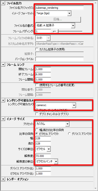
Perform rendering
The results of rendering are shown below. If Frame 5 and Frame 6 are rendered well, the orientation of the image does not need to be corrected.

Combine these six images using Photoshop.
Lock the grid and arrange the cube map.

Check the texture using CreativeStudio
Check that the characters can be read correctly.
First, we recommend testing the cube map using a scene where directions are easy to determine.


Creating Using Photoshop
Creating a cube map from an image
With this method, the image is created by drawing it yourself or processing a photograph.

Create an image for the horizontal direction (or prepare a photograph)
Conditions are: the horizontal must be a power of two, the ratio between vertical and horizontal must be 1:4, and left and right directions must connect.
Prepare images for the top and bottom
Make the image size 300% in the vertical and prepare images for the top and bottom. At this point, the four edges of the top and bottom images must connect to the central image.
Save the file
Use the ETC1 format since the image size of cube maps can become quite large.
Check the texture using CreativeStudio