| Types of Reception Strength Icons | StreetPass | ||||
|---|---|---|---|---|---|
| Internet (including NintendoZone) |
Local Communications | Wireless ON. | Wireless OFF | ||
| Level 1 |  |
 |
 |
 |
 |
| Level 2 |  |
 |
 |
||
| Level 3 |  |
 |
 |
||
| Level 4 |  |
 |
 |
||
This document describes graphics data specifications for communication icons used on the CTR HOME Menu. The following icon patterns, indicating the four communication modes, may be used for the communication icon. The sections to follow will describe precautions and how to use communication icons in each communication mode.
Table 1-1 All 14 Communication Icon Patterns
| Types of Reception Strength Icons | StreetPass | ||||
|---|---|---|---|---|---|
| Internet (including NintendoZone) |
Local Communications | Wireless ON. | Wireless OFF | ||
| Level 1 | |
|
|
|
|
| Level 2 | |
|
|
||
| Level 3 | |
|
|
||
| Level 4 | |
|
|
||
With the CTR, you can return to the HOME Menu any time while an application is running. Because you can check the reception mode and reception strength on the HOME Menu, applications are not required to display communication icons. If you are displaying communication icons for an application, you are not required to use the communication icons supplied with CTR-SDK. As such, there is no problem creating your own communication icons to match the look and feel of your application. Furthermore, there is no problem with not displaying communication icons depending on software attributes.
If you use the communication icons supplied in CTR-SDK with an application, be sure to implement them so that their behavior is the same as the communication icons found on the HOME Menu. Otherwise, the user may become confused as to why the behavior of icons within the application differs from that of icons on the HOME Menu even though they appear to be identical. Make sure that behavior is consistent in order to avoid such confusion. For details, see the display of each icon described later and the functions related to their display.
The reception strength icons indicate both the current communication mode and signal status.
Use the following four icons when performing communications in infrastructure mode (Internet communications). These icons are also used when communicating with Nintendo Zone.
Figure 3-1 Icons for Internet Communication
Each icon shows one of four possible signal strenghs. Icons to the right indicate better signal strength. During implementation, make the display change according to the value returned by the nn::ac::CTR::LinkLevel function.
Return value of the nn::ac::CTR::LinkLevel function |
Icon |
|---|---|
LINK_LEVEL_0 |
|
LINK_LEVEL_1 |
|
LINK_LEVEL_2 |
|
LINK_LEVEL_3 |
|
Use the following icons during UDS communication.
Figure 3-2 Icons for Local Communication
Each icon shows one of four possible signal strenghs. Icons to the right indicate better signal strength. During implementation, make the display change based on the value returned by the nn::ac::CTR::LinkLevel function the same way as the internet communication.
Use this icon when the wireless switch on the CTR is on, but none of the three communication modes described previously (Internet, StreetPass, or Local) are currently being used.
Figure 3-3 Icon Used When the Wireless Switch Is ON but No Communication Is Being Performed
Signal status is not indicated in this mode.
Use this icon when the wireless switch on the CTR is OFF. Use the nn::nwm::CTR::GetCommuniationMode function for getting the current wireless mode when determining if the wireless switch is OFF. Display this icon when the return value of the function is WIFIOFF_MODE.
Figure 3-4 Icon Used When the Wireless Switch Is OFF
Use StreetPass communication icons to indicate that StreetPass communication is enabled. Unlike the reception strength icons described previously, these icons do not indicate signal strength. These icons are used to indicate that StreetPass communication is enabled.
Figure 4-1 Icons for StreetPass Communication
Use a loop animation made up of the four patterns above when displaying this information. Display them in a loop that repeats in the order of 0 bars, 1 bar, 2 bars, and then 3 bars every 60 f (1 sec).
Distributed communication icon data is provided in .psd format. Convert this data to the format best suited for your application development environment. Image data files are located in the following directory in CTR-SDK. $CTR_SDK/resources/icon/ConnectionIcon
The layer configuration of .psd files is as follows. The Dummy layer does not need to be output. 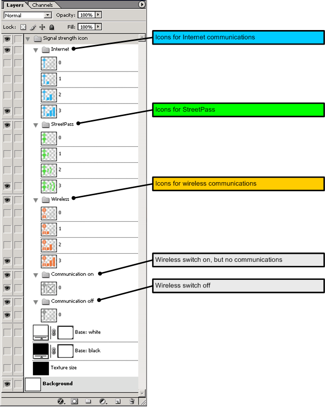
Icons cannot be modified. Do not switch to original colors or make changes to the image pattern.
There is no problem with adding a mask to the icon background for the purpose of increasing icon visibility. There are no specifications or restrictions on the design of this mask.
CONFIDENTIAL