StereoCameraCalibrator is a tool for manually setting the calibration data for the stereo cameras. This tool can set the following values.
Position offsets
| Parameter Name | Setting Name in the Tool | Member in StereoCameraCalibrationData Structure |
|---|
| Scaling factor | scale | scale |
| Angle of rotation around the light axis | rotZ | rotationZ |
| Amount of horizontal translation | transX | translationX |
| Amount of vertical translation | transY | translationY |
Angles of view
| Parameter name | Item name in the tool | Member in StereoCameraCalibrationData Structure |
|---|
| Angle of view of the left camera | angleL | angleOfViewLeft |
| Angle of view of the right camera | angleR | angleOfViewRight |
Note: Any values configured with this tool will be reset to their factory defaults if you run the
Config tool and reset settings.
Preparing the Chart
Print the chess chart (chesschart-14mm-16x10.pdf) stored in the documents/api/tools folder. Place this chart 250 mm away from the CTR camera module. Both the camera and the chart must be horizontal.
Note that the calibrated values will be erroneous if the distance between the camera module and the chart is not 250 mm, or if the camera module and chart are not both horizontal.
Note:
Be sure to print the chart at actual size, because any scaling will make correct calibration impossible.
Calibrating the Values
Use Left/Right on the +Control Pad to select the setting to calibrate, then use Up/Down to change its value. (For example, if you press Right on the +Control Pad while rotZ is selected, the cursor moves to transX on the next line.))
Adjust the values of scale, rotZ, transX, and transY so that the chess chart in the left image exactly overlaps the chess chart in the right image. For how to set angleL and angleR, see How to Set the Angles of View.
Setting the Parameters
Press the A Button to save all the calibrated values to the system as calibration data. Note that all the calibration values are saved at once, not just the setting you have currently selected.
Press the B Button to cancel any adjustments you have made to the selected setting and reset it to its original value (the value saved in the system).
Preparing the Chart
Just as when calibrating the position offsets, print the chess chart (chesschart-14mm-16x10.pdf) stored in the documents/api/tools folder. Place this chart 250mm away from the CTR camera module.
Calibrating the Values
To calibrate the left camera's angle of view, select angleL and press the B Button. To do the same for the right camera, select angleR and press the B Button.
The upper screen displays only the image for the selected side, overlaid with two square icons. The calibration value is the default value: 66.0.
If you adjust the value with Up/Down on the +Control Pad, the two icons overlaid on the image move closer or farther apart. Adjust the distance between these two icons so that they lie exactly on two squares of the chess chart whose centers are 84mm apart. Each square is 14 mm wide, so the squares you want the icons to lie on have 5 full squares between them.
(See figure below.)
Adjust the value so that the icons lie exactly on the two end squares.
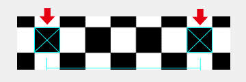
If the size of the chess square does not perfectly match the size of the icon, align the center of the icon with the center of the square.
You can also use the Circle Pad to change the position of the icons. When you are making very fine adjustments, we recommend moving the icons rather than moving the camera module or the chart.
Setting the Parameters
Press the A Button to save all the calibrated values to the system as calibration data. Note that all calibration values are saved, not just the setting you have currently selected.
Press the B Button to cancel any adjustments you have made to the selected settings and reset them to the original values.